
Introduction
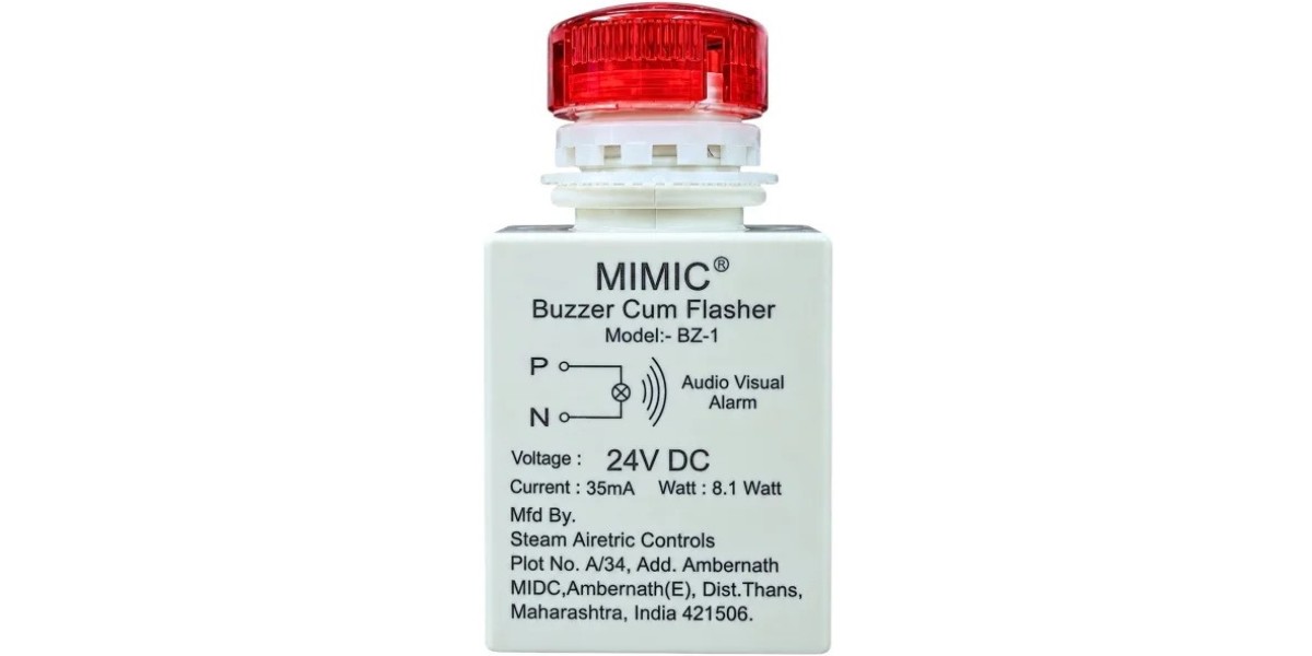
A Buzzer cum flasher combines an audible warning with a flashing visual indication. Like other electrical components, it needs correct installation, suitable operating conditions, and periodic inspection. Maintenance should consider not only the device itself but also the circuit that activates it.
A structured inspection routine can help identify faults before they affect normal operation. It also helps maintenance teams distinguish between a problem with the sounder or flashing element and an issue elsewhere in the control circuit.
Why Maintenance Matters
An alarm system is useful only when it operates when required. A damaged housing, loose connection, incorrect supply, failed component, or faulty control signal can prevent the warning from functioning as intended.
A device may also become less effective without completely failing. For example, a flashing lens may be obscured by dirt, or the sound may be difficult to hear because of a change in background noise or the installation environment. These issues can reduce the likelihood that an operator will notice the warning.
Regular inspection helps maintain confidence in the alarm system. It should be planned according to the equipment manufacturer's instructions, the importance of the warning, the site's operating conditions, and the organisation's maintenance procedures.
Understand the Complete Alarm Circuit
Before investigating a fault, it is important to understand how the warning is activated. A buzzer cum flasher is often connected to a control circuit that receives a signal from a relay, controller, sensor, or other device.
If the alarm does not operate, the cause may not be the warning unit itself. The triggering condition may not have occurred, the control output may be inactive, a protective component may have opened the circuit, or a wiring issue may interrupt the supply.
A simple functional diagram can help technicians understand the relationship between the initiating condition, the control logic, and the warning device. The documentation should identify the relevant terminals, supply rating, protection, and any acknowledgement or reset arrangement.
Troubleshooting without understanding the circuit can lead to unnecessary component replacement or unsafe attempts to bypass a fault.
Routine Visual Inspection
A visual inspection is a useful starting point when carried out under the site's safe maintenance procedure. The equipment should be isolated where required, and personnel should follow the appropriate precautions before touching the device or its wiring.
Inspect the external housing for cracks, discolouration, signs of overheating, loose mounting, or other visible damage. Check whether the visual lens is clean and unobstructed. Dust, labels, nearby equipment, or changes to the panel layout may reduce visibility.
The mounting should remain secure. Excessive movement or vibration may place stress on the wiring and connections. The panel should also be checked for signs of moisture ingress or contamination where these are relevant to the installation.
Any damage or condition outside the manufacturer's permitted limits should be assessed before the device is returned to service.
Testing the Audible Function
The audible signal should be tested using an approved procedure that activates the alarm under controlled conditions. Personnel should be aware that the test may sound in the surrounding area, and the process should be planned to avoid unnecessary confusion or disruption.
If the sound is absent or noticeably different from the expected behaviour, several causes may need consideration. The supply could be incorrect, the activation circuit may not be operating, a connection may be loose, or the sound-producing component may have failed.
The technician should compare the observed behaviour with the product documentation and circuit diagram. Testing should not involve random changes to wiring or the application of an unverified voltage.
Where the device operates but the sound is not clearly noticed from the operator's position, the issue may relate to the installation environment rather than the component alone. Background noise, distance, partitions, and hearing protection can affect how the signal is perceived.
Testing the Flashing Indication
The visual part should also be checked during a functional test. Confirm that the indication activates as expected and that the light is clearly visible from the relevant viewing position.
A flashing element that does not operate may indicate a problem with the device, the supply, the connection, or the control arrangement. If the light operates intermittently when it should be consistent, the cause should be investigated rather than dismissed as a minor inconvenience.
The visual indication should not be judged only from directly in front of the device. The intended viewing angle and surrounding lighting matter. Bright ambient light, reflections, obstructions, or a crowded panel may make an otherwise functioning indication difficult to notice.
The test should establish whether the warning is visible under the conditions in which the equipment normally operates.
Check Supply and Wiring Compatibility
Electrical faults can cause symptoms that resemble device failure. Incorrect supply voltage, a mismatch between AC and DC requirements, loose terminals, damaged conductors, or a fault in the control output may prevent proper operation.
Qualified personnel should compare the installed wiring with the approved diagram and verify the device's rating. Any electrical measurements must be made using the correct instruments and safe procedures.
Connections should be checked for security and signs of heat damage, corrosion, or mechanical strain. Conductors must be appropriate for the terminal design and the circuit requirements. The technician should also confirm that the specified circuit protection is present and suitable.
A component should not be replaced with a different model simply because it fits the same opening. The replacement must meet the electrical, mechanical, and environmental requirements of the application.
Troubleshooting Common Symptoms
The sound and light are both absent
The issue may involve the incoming supply, a disconnected control signal, an open circuit, or the warning unit itself. Begin with the circuit documentation and approved diagnostic procedure.
The sound works, but the light does not flash
Possible causes include a fault in the visual element, an internal component failure, or a problem affecting the flashing function. Confirm the model's expected behaviour before deciding that a replacement is necessary.
The light flashes, but there is no sound
The audible component may have failed, or the unit may not be receiving the conditions required for both functions. The device and its circuit should be checked against the manufacturer's information.
The alarm operates at unexpected times
This may be related to the initiating signal, controller logic, relay contacts, or an intermittent electrical connection. Review the control circuit and any recorded fault history before changing settings.
The alarm is hard to notice
The device may be positioned poorly, its lens may be obscured, or the background environment may have changed. Evaluate the operator's actual viewing and listening conditions before deciding whether relocation or a different warning arrangement is required.
These symptoms are starting points for investigation, not definitive diagnoses. The correct cause must be established through safe testing.
Keep Maintenance Records
Maintenance records help identify recurring issues and demonstrate that required checks have been completed. A useful record can include the inspection date, device identification, observed condition, test result, corrective action, and name or role of the responsible technician.
If the same alarm repeatedly fails, reviewing the history may reveal a pattern. For example, repeated loose connections may indicate vibration or poor cable support, while frequent false activations may point to an issue in the initiating circuit or alarm logic.
Records can also help when a control panel is modified. If a device is moved, replaced, or connected to a different control output, the documentation should be updated to reflect the actual installation.
Avoid Unsafe Maintenance Practices
Do not bypass a warning circuit simply to keep equipment running unless a formally authorised procedure specifically permits a controlled temporary arrangement. If an alarm has an important operational or safety role, a failed device should be reported and assessed.
Electrical work should be undertaken by qualified personnel using the site's isolation and verification procedures. A warning device must not be opened, rewired, or tested in an unsafe condition. Nor should an operator assume that silencing an alarm has corrected the underlying fault.
If the alarm is part of a safety-related system, any change to the circuit must be assessed under the relevant engineering and safety process.
FAQs
1. How often should a buzzer cum flasher be tested?
Follow the manufacturer's recommendations and the site's maintenance plan. The required frequency depends on the importance of the warning and the operating environment.
2. What should be checked if the alarm does not activate?
Check the documented activation condition, supply, control signal, wiring, and device using the approved diagnostic procedure.
3. Can dirt affect the warning function?
Yes. Dirt or obstructions can reduce the visibility of the flashing indication. Contamination may also contribute to damage if the device is used outside its environmental limits.
4. Should a faulty alarm be ignored if the machine still runs?
No. Report the issue and follow the site's procedures. The consequences of an unavailable warning should be assessed before the system continues operating.
5. Can the same device always be used as a replacement?
No. The replacement must match the required electrical ratings, mounting arrangement, environmental conditions, and alarm behaviour.
6. Why are maintenance records useful?
They document inspection and testing, help identify repeated failures, and provide information for future troubleshooting and system modifications.
Summary
Maintaining a buzzer cum flasher involves inspecting its physical condition, testing both audible and visual indications, checking electrical compatibility, and verifying the complete activation circuit. Troubleshooting should follow the approved documentation rather than rely on guesswork. Regular testing and accurate maintenance records help reveal problems early and support reliable warning performance. When an alarm fails, the cause should be investigated and the risk assessed instead of treating the warning as an optional accessory.